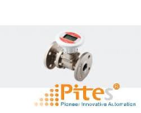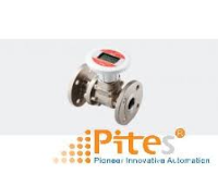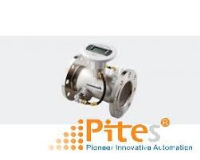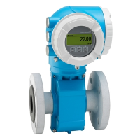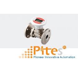
Aichi Tokei Denki VietNam, AS-W-40, Cảm biến lưu lượng siêu âm cho khí ga AS-W-40, Đại lý Aichi Tokei Denki VietNam
Nhà cung cấp: Pitesco
Hãng sản xuất: Aichi Tokei Denki
Aichi Tokei Denki VietNam, AS-W-40, Cảm biến lưu lượng siêu âm cho khí ga AS-W-40, Đại lý Aichi Tokei Denki VietNam
AS-W Series
Since AS-W flow meter covers wider range from small to large flow rate, it contributes to cost saving and convenient facility management. At the same time, it saves the cost of redundant governor and piping.
・ Non-moving parts results in not degrading meter performance. It eventually makes needless to repair the parts and refuel the lubricant oil.
・ Because of the pressure loss being closely “0”, it can get rid of the pressure shortage risk.
・ Because of lightweight and compact feature, it enables easy installation and needs less space.
Product Specifications
| Model | AS-W-25 | AS-W-32 | AS-W-40 | AS-W-50 | AS-W-80 | AS-W-100 | AS-W-150 | AS-W-200 | |||
|---|---|---|---|---|---|---|---|---|---|---|---|
| Nominal diameter | 25A | 32A | 40A | 50A | 80A | 100A | 150A | 200A | |||
| Power supply | Built-in lithium batteries | ||||||||||
| Years of duration | 6 years (At surrounding temperature of 20℃) (Exclunding 1 year of storage period) |
||||||||||
| Measurable fluids | Natural gas and air | ||||||||||
| Working pressure (Absolute pressure) |
0∼0.5MPa(AS-WW-□-500B[A/G]/3) 0∼0.2MPa(AS-WW-□-200B[A/G]/3) 0∼0.5MPa(AS-WW-□-0B[A/G]/3) |
0∼1.0MPa(AS-WW-□-1000B[A/G]/3) 0∼0.5MPa(AS-WW-□-500B[A/G]/3) 0∼0.2MPa(AS-WW-□-200B[A/G]/3) 0∼1.0MPa(AS-WW-□-0B[A/G]/3) |
|||||||||
| Accuracy | Flowrate measurement accuracy *1 | ±5%RS (m³/h) | Actual flow rate (m³/h) | ±0.7 ∼ 7 | ±1.3 ∼ 13 | ±1.6 ∼ 16 | ±3 ∼ 30 | ±6 ∼ 60 | ±10 ∼ 100 | ±24 ∼ 240 | ±40 ∼ 400 |
| ±2%RS (m³/h) | Actual flow rate (m³/h) | ±7 ∼ 35 | ±16 ∼ 65 | ±16 ∼ 80 | ±30 ∼ 150 | ±60 ∼ 300 | ±100 ∼ 500 | ±240 ∼ 1200 | ±400 ∼ 2000 | ||
| Low flow cut-off (Initial flow rate) *2 |
Flow rate (m/s) | 0.05 m/s or less | |||||||||
| Actual flow rate (m³/h) | ±0.1 | ±0.2 | ±0.2 | ±0.4 | ±0.8 | ±1.5 | ±3.2 | ±5.7 | |||
| Fluid temperature and humidity | -20 to +60℃, 90% RH or less | ||||||||||
| Pressure loss | Zero (Equivalent to straight tube part) | ||||||||||
| Display | Accumulated flow volume | Accumulated flow volume: 00000000.0 (9 digits/m³ or Nm³) | Accumulated flow volume: 0000000000 (10 digits/m³ or Nm³) | ||||||||
| Instantaneous flow rate *3 | (1) Maximum indication value: ±19999Nm³/h (converted flow rate) (2) Maximum indication value: ±19999Nm³/h (actual flow rate) (Two decimal places for a value less than 200, one decimal place for a value from 200 to less than 2000, integer only for a value of 2000 or more) |
||||||||||
| Temperature *3 | 00.0℃ (3-digits) | ||||||||||
| Pressure *3 | 0000.0kPa (5-digits) | ||||||||||
| Output | Contact output | Open drain output: Unit pulse (forward flow) Pulse unit: 100,1000,10000 (L/P or NL/P) |
|||||||||
| Telegram output | RS485 Modbus/RTU | ||||||||||
| Connection method | ISO7-1 Taper screw connection(JISB 0203, BS21, GB/T7306, 2-2000) equivalent | ISO7005-1 (GB/T9119-2002 PN1.6MPa Flange) equivalent *4 | |||||||||
| Installation position | Horizontal and vertical | ||||||||||
| Installation location | Indoor and outdoor (protection level IP 64 or equivalent) | ||||||||||
| Case material | Aluminum alloy | Stainless alloy | |||||||||
| The materials exposed to gases | Aluminum alloy and engineering plastic | Stainless alloy and engineering plastic | |||||||||
| Mass | 1.8kg | 1.7kg | 7.6kg | 9.6kg | 13.3kg | 13.2kg | 20.4kg | 35.4kg | |||
*1. The flow rate measurement range is ±5% RS: Inclusive before “∼” and not inclusive after “∼” and ±2% RS: Inclusive for both before and after “∼”.
*2. When the flow rate is less than 0.25% of the maximum flow rate, the instantaneous flow rate is indicated as 0 m³/h. For the normal conversion type, the low flow cut off value is the normal conversion flow rate corresponding to 0.05 m/s.
*3. Automatically switched in every 4 seconds.
*4. This flowmeter guarantees the flow measurement accuracy with the pipes listed in the table below.
(If you use pipes with the different pipe standard and size not listed in the table, the flowmeter may not satisfy the flow measurement accuracy. Consult us in advance if it is considered to use different pipes out of this range.)
| Pipe standard | G3459 JIS 10K | EN10208 | ||||||
|---|---|---|---|---|---|---|---|---|
| Nominal diameter(mm) | 25 | 32 | 40 | 50 | 80 | 100 | 150 | 200 |
| External diameter(mm) | 34 | 42.7 | 48.3 | 57 | 88.9 | 108 | 159 | 219.1 |
| Thickness(mm) | 2.8 | 2.8 | 4 | 3.5 | 4.5 | 4 | 4.5 | 10 |


 Mr Ha
Mr Ha