NW/NW-PInstantaneous Flow-rate/ Integrating Flow Volume Flowmeter_cảm biến đo lưu lượng Aichi Tokei Denki Vietnam
Xuất sứ: Nhật Bản
Nhà cung cấp: Pitesco
Hãng sản xuất: Aichi Tokei Denki
 Mr Ha
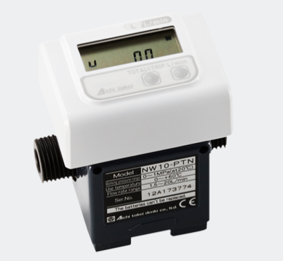
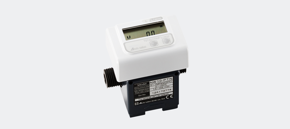
Mr HaNW/NW-PInstantaneous Flow-rate/
Integrating Flow Volume Flowmeter
Feature
・Built-in lithium batteries (No external power supply is required)
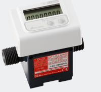
・Indications of both instantaneous flow-rate and integrating flow volume by only 1 flowmeter
・Revolving display unit (It can be fixed to a easy-to-read position)
・Simplified structure with the vane wheel type measuring principle
・Measurement of various liquids
・Reset function for indications of Integrating Flow Volume (Total) and Integrating Flow Volume (Trip)
・Value holding function for Instantaneous Flow-Rate indication
・Pulse output function (Option)
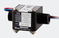
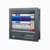
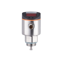
Model NW (Local display type)
Model NW-P (With pulse output)
Enhanced basic functions, user friendliness and cost efficiency are the key points
ND series offers high accuracy measurement of not only cold and warm water but also pure water, chemical fluids, etc. It is light-weighted compact body and is compatible with various kinds of fluids with the carefully selected casing materials such as PP, ETFE, PPO, etc., and with the highly sensitive magnetic sensor of our own development. This series is therefore widely applicable for various flow measurements and its control and monitoring as well.
Flowsensor Applications
・To control of warm water temperature
・To constantly supply water and warm water
・To monitor coolant, etc.
・To proportionally inject chemical fluids
・To control pressure loss of filters
Specifications
| Instantaneous flow-rate· Integrating flow volume flowmeter NW Type |
NW05-NTN | NW05-PTN | NW05-TTN | NW10-NTN | ||
|---|---|---|---|---|---|---|
| Instantaneous flow-rate· Integrating flow volume flowmeter (with pulse output) NW-P Type |
NW05-NTP | NW05-PTP | NW05-TTP | NW10-NTP | ||
| Flow-rate range (m3/h) | 0.3 – 3L/min | 1.5 – 20L/min | ||||
| Accuracy | Flow-rate indication | ±2%RS±0.05L/min | ±2% RS±0.2L/min |
|||
| Volume indication | ±2%RS (with the standard installation position) | |||||
| Measurable fluids | Various liquids (Please select with reference to the following major materials of the liquid-touching materials) |
|||||
| Max. Working Pressure | 1MPa (at the time of fluid temperature of 20°C) | |||||
| Pressure Drop | Not more than 12kPa (At the time of 3L/min) |
Not more than 20kPa (At the time of 20L/min) |
||||
| Fluid viscosity range | 0.5-1.5mPa・s | |||||
| Fluid temperature range | 0±60°C | |||||
| Ambient temperature range | 0±60°C 35-85%RH(Dew condensation must be avoided) | |||||
| Output signal (for NW-P) | Open drain output (Equivalent to open collector) Pulse width: Not less than 5ms Max. rating voltage: 30 VDC Output capacity: “ON resistance” Not more than 150Ω, “OFFresistance” Not less than 100kΩ (Remained voltage not morethan 1.5V in case of input current not more than 10mA) |
|||||
| Pulse unit (for NW-P) | 10mL/p | 1L/p | ||||
| LCD | Flow-rate | Smallest Scale | 0.05L/min | 0.2L/min | ||
| Display digits | 00.00L/min | 000.0L/min | ||||
| Volume | Display digits | 000000.00L | 0000000.0L | |||
| Power supply | Built-in lithium battery (Battery life 4 years. Not replaceable.) | |||||
| Measurable fluids | Refer to “MEASURABLE FLUID AND PARTS MATERIALS” | |||||
| Structure | IP64 equivalent, Indoor installation | |||||
| Connection | R1/2 | |||||
| Meter Weight | Approx. 280g | Approx. 250g | ||||
| Major materials of the liquid touching parts |
Casing | Denatured PPO |
PP | ETFE | Denatured PPO |
|
| Vane wheel | POM | ETFE | POM | |||
| Pivot | SUS304 | PA | ETFE | SUS304 | ||
| O-ring | NBR | FKM | NBR | |||
| Magnet | Sa-Co *1 | Ba-Fe | ||||
| Instantaneous flow-rate· Integrating flow volume flowmeter NW Type |
NW10-PTN | NW10-TTN | NW20-NTN | NW20-PTN | ||
|---|---|---|---|---|---|---|
| Instantaneous flow-rate· Integrating flow volume flowmeter (with pulse output) NW-P Type |
NW10-PTP | NW10-TTP | NW20-NTP | NW20-PTP | ||
| Flow-rate range (m3/h) | 1.5-20L/min | 1.0-10L/min | 3.0-60L/min | |||
| Accuracy | Flow-rate indication | ±2%RS±0.2L/min | ±2% RS±0.5L/min | |||
| Volume indication | ±2%RS (with the standard installation position) | |||||
| Measurable fluids | Various liquids (Please select with reference to the following major materials of the liquid-touching materials) |
|||||
| Max. Working Pressure | 1MPa (at the time of fluid temperature of 20°C) | |||||
| Pressure Drop | Not more than 20kPa (At the time of 20L/min) |
Not more than 15kPa (At the time of 10L/min) |
Not more than 60kPa (At the time of 60L/min) |
|||
| Fluid viscosity range | 0.5-1.5mPa·s | |||||
| Fluid temperature range | 0±60°C | |||||
| Ambient temperature range | 0±60°C 35-85%RH(Dew condensation must be avoided) | |||||
| Output signal (for NW-P) | Open drain output (Equivalent to open collector) Pulse width: Not less than 5ms Max. rating voltage: 30 VDC Output capacity: “ON resistance” Not more than 150Ω, “OFF resistance” Not less than 100kΩ (Remained voltage not more than 1.5V in case of input current not more than 10mA) |
|||||
| Pulse unit (for NW-P) | 1L/p | |||||
| LCD | Flow-rate | Smallest Scale | 0.2L/min | 0.5L/min | ||
| Display digits | 000.0L/min | |||||
| Volume | Display digits | 0000000.0L | ||||
| Power supply | Built-in lithium battery (Battery life 4 years. Not replaceable.) | |||||
| Measurable fluids | Refer to “MEASURABLE FLUID AND PARTS MATERIALS” | |||||
| Structure | IP64 equivalent, Indoor installation | |||||
| Connection | R1/2 | R3/4 | ||||
| Meter Weight | Approx. 250g | Approx. 500g | ||||
| Major materials of the liquid touching parts |
Casing | PP | ETFE | Denatured PPO |
PP | |
| Vane wheel | POM | ETFE | POM | |||
| Pivot | SUS304 | ETFE | SUS304 | |||
| O-ring | FKM | NBR | FKM | |||
| Magnet | Ba-Fe | Sa-Co *1 | Ba-Fe | |||
Any installation position other than the standard installation position is not available for NW05-TTN, NW05-TTP, NW10-TTN, and NW10-TTP.
*1: The magnet does not touch liquid.
Dimensions
| Mode | NW05 | NW10 | NW20 |
|---|---|---|---|
| A(mm) | 80 | 80 | 110 |
| B(mm) | 87 | 87 | 105.5 |
| C(mm) | 52 | 52 | 74 |
| D(mm) | 11 | 11 | 16 |
| E(mm) | 25 | 25 | 35.5 |

Standard installation position
The standard installation position is that the display is facing upwards.
* The display is able to be revolved.

Materials -Abbreviations
| Denatured PPO | Denatured Polyphenylene oxide |
|---|---|
| PP | Polypropylene |
| ETFE | Ethylene-tetrafiuoro ethylene |
| POM | Polyacetal or Polyoxymethylene |
| SUS304 | Stainless steel 304 |
| PA | Polyamide |
| NBR | Acrylonitrile-Butadiene Rubber |
| FKM | Fluoro Rubber |
| Sa-Co | Samarium-Cobalt |
| Ba-Fe | Barium-ferrite |
Handling Instructions
Observe the following handling instructions and precautions to obtain maximum performance of the Flowsensor / Flowmeter.
CAUTIONS IN MOUNTING
1. The flowing direction of the fluid, when mounting, must be matched to the arrow mark on the case that indicates the direction of flow.
2. A straight pipe with uniform inner diameter must be connected to the inlet. Accuracy is adversely affected if the pipe is bent or the inner diameter is uneven.
3. The inner diameter of the inlet pipe must be greater than the nozzle diameter of the Flowsensor / Flowmeter.
| Type | Inner D, of inlet pipe | Length of straight pipe at inlet |
|---|---|---|
| ND05,NW05 | 5.5 mm or greater | Greater than 50 mm from the end of the Flowsensor / Flowmeter |
| ND10,NW10 | 10.5 mm or greater | Greater than 100 mm from the end of the Flowsensor / Flowmeter |
| ND20,NW20 | 15.5 mm or greater |
4. If pulsation occurs in the flow of the fluid, measurement accuracy is adversely affected. When a pump is used to circulate the fluid, an accumulator must be provided to remove the pulsation.
5. Be careful not to apply excessive stress on the Flowsensor / Flowmeter during installation.
6. Make sure to provide thermal insulator at places subject to freezing in winter. When leakage occurs due to half frozen fluid, accuracy is adversely affected.
7. Do not expose/install the Flowsensor / Flowmeter under direct sunshine.
8. The measuring range, operating pressure and operating temperature are indicated on the plate on the side of the Flowsensor / Flowmeter. Observe these conditions for optimum performance of the Flowsensor / Flowmeter.
9. Avoid locating the Flowsensor / Flowmeter at places subject to excessive pressure and stress such as water hammer by operating components.
10. When air enters the Flowsensor / Flowmeter, measurement accuracy is influenced. Always operate the Flowsensor / Flowmeter chamber full of fluid. To maintain high accuracy, avoid mixture of air to the fluid.
11. Avoid placing a strong magnetic material or magnetic field near the Flowsensor / Flowmeter.
12. Installation position is flexible except those shown in figures on the upper right. However, it is recommended to install the Flowsensor / Flowmeter at the standard position whenever possible. For types ND 05-TATAAA, ND10-TATAAA, NW05-TTN, NW10-TTN, installation must be at standard positions.
Standard mounting position

CONNECTION (WIRING)

Measurable fluids and parts materials
MEASURABLE FLUIDS
1.Fluid which done not corrode materials that contact the fluid.
2.Viscosity of the fluid to be measured is between 0.5 and 1.5cp.
3.No slurry is contained.
4.Particles attracted by magnetic power such as iron, is contained in the fluid.
(All of the above 1-4 must be satisfied.)
LIST OF MATERIALS THAT CONTACT FLUIDS DIRECTLY
The table below shows components and materials of the standard type Flowsensor / Flowmeter used in portions that come into direct contact with the fluid.
| Parts name | Model | |||||
|---|---|---|---|---|---|---|
| ND05-PATAAC NW05-PTN NW05-PTP |
ND05-NATAAC NW05-NTN NW05-NTP |
ND05-TATAAA NW05-TTN NW05-TTP ND10-TATAAA NW10-TTN NW10-TTP |
ND10-PATAAA NW10-PTN NW10-PTP |
ND20-PATAAA NW20-PTN NW20-PTP |
ND10-NATAAA NW10-NTN NW10-NTP ND20-NATAAA NW20-NTN NW20-NTP |
|
| Lower casing Upper casing Regulator |
PP | Denatured PPO | ETFE | PP | PP | Denatured PPO |
| Vane-wheel | POM | POM | POM | POM | POM | |
| Pivot | PA | SUS304 | PA | SUS304 | SUS304 | |
| O-ring | FKM | NBR | FKM | FKM | FKM | NBR |
| Magnet | Samarium cobalt (No contact with fluid) | Samarium cobalt (No contact with fluid) | Samarium cobalt (No contact with fluid) | Ba-Fe | Ba-Fe | Ba-Fe |
| Measurable fluid | Water, Chemical fluid (Weak corrosion resistance) |
Water, Warm Water |
Chemical fluid | Water, Chemical Fluid (Weak corrosion resistance) |
Water, Warm Water |
|
Material Code
・Ba-Fe: Barium-Ferrite
・ETFE: Ethylene-tetrafluoro ethylene
・FKM: Fluoro Rubber
・NBR: Acrylonitrile-butadiene rubber
・PA: Polyamide
・POM: Polyacetal or Polyoxymethylene
・PP: Polypropylene
・PPO: Polyphenylene oxide
・SUS304: Stainless steel